|
Network Management requires that the user is a valid ArcGIS user that has access to the ArcGIS Advanced Editing user type extension. Note that ESRI licensing may change over time. Please refer to these pages for more information: https://www.esri.com/en-us/arcgis/products/user-types/overview https://enterprise.arcgis.com/en/portal/latest/administer/windows/license-user-type-extensions.htm |
|---|
The Network Management module completes the 360° functionality required for managing linear assets in the utility network domain. It is specifically designed to support gas, electrical, and water utility companies using the ESRI Utility Network data model. This module empowers users to edit linear assets and provides powerful tools for network tracing, associations, and topology validation.
Key Features
-
Utility Network Integration:
The module supports the ESRI Utility Network data model, enabling seamless editing and visualization of linear assets.
-
Configurable Setup:
Administrators can configure the module effortlessly in the Control Panel by:
-
Selecting a compatible web map following the Utility Network data model.
-
Setting the Opening Mode to Exclusive (recommended). This ensures the user session is saved, allowing users to focus on a specific task independently.
-
One-Click Access:
With a single click, users can access the Network Management mode. This loads the configured network map and displays detailed information about the network.
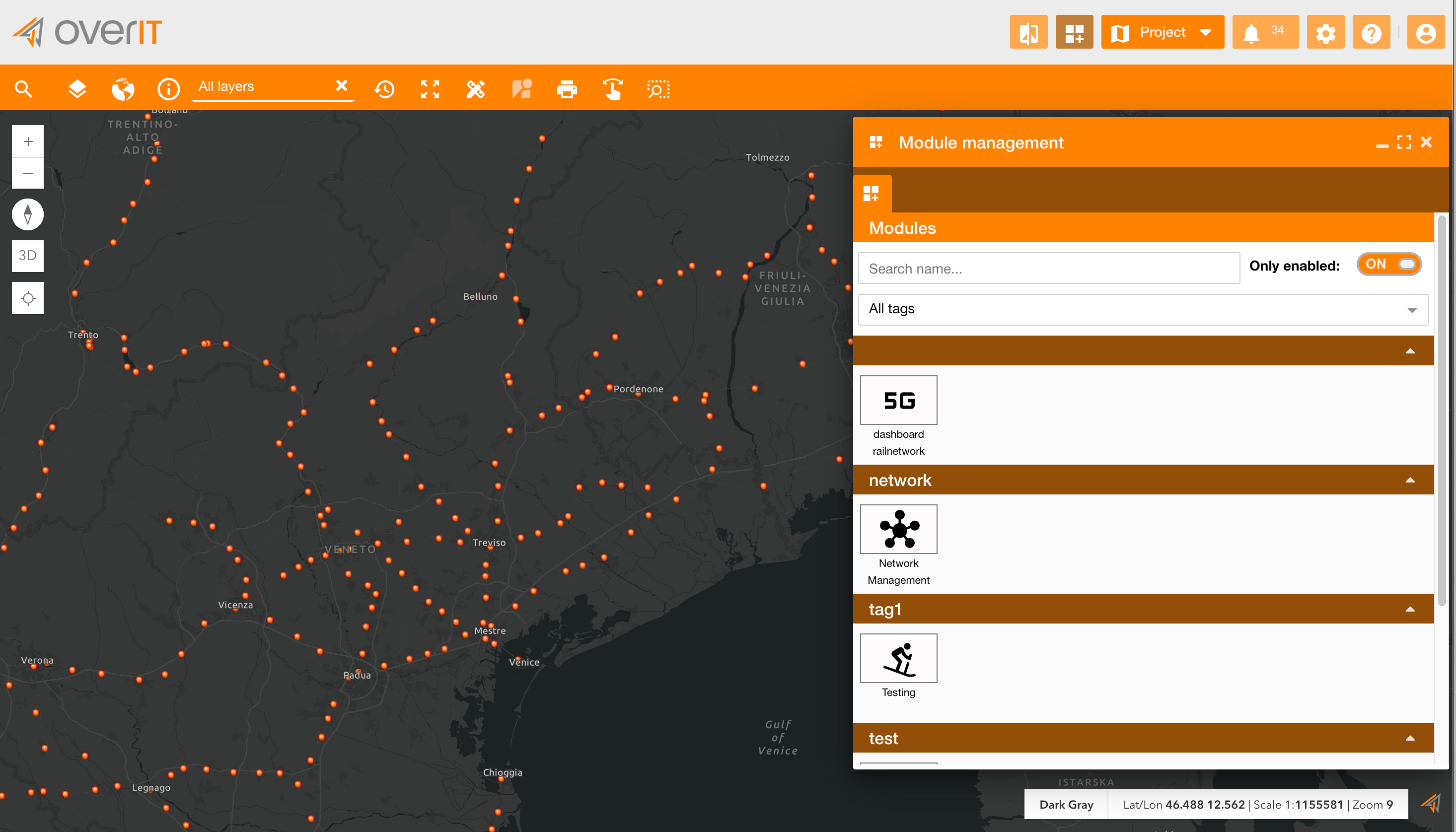
-
Focused User Workflow:
The exclusive mode ensures users can concentrate on the network task without distractions from other application modules.
Module Overview
The module window comprises three main tabs:
1. Trace
The Trace tab enables users to perform network tracing operations. Network tracing is the process of analyzing connectivity within the utility network. It helps determine how elements in the network are connected and affected by each other, such as:
-
Identifying upstream or downstream elements.
-
Locating affected areas during outages or maintenance.
-
Analyzing resource flow (e.g., gas, water, or electricity).
Based on your explanation and the images provided, here is the updated Network Management module documentation in Markdown format:
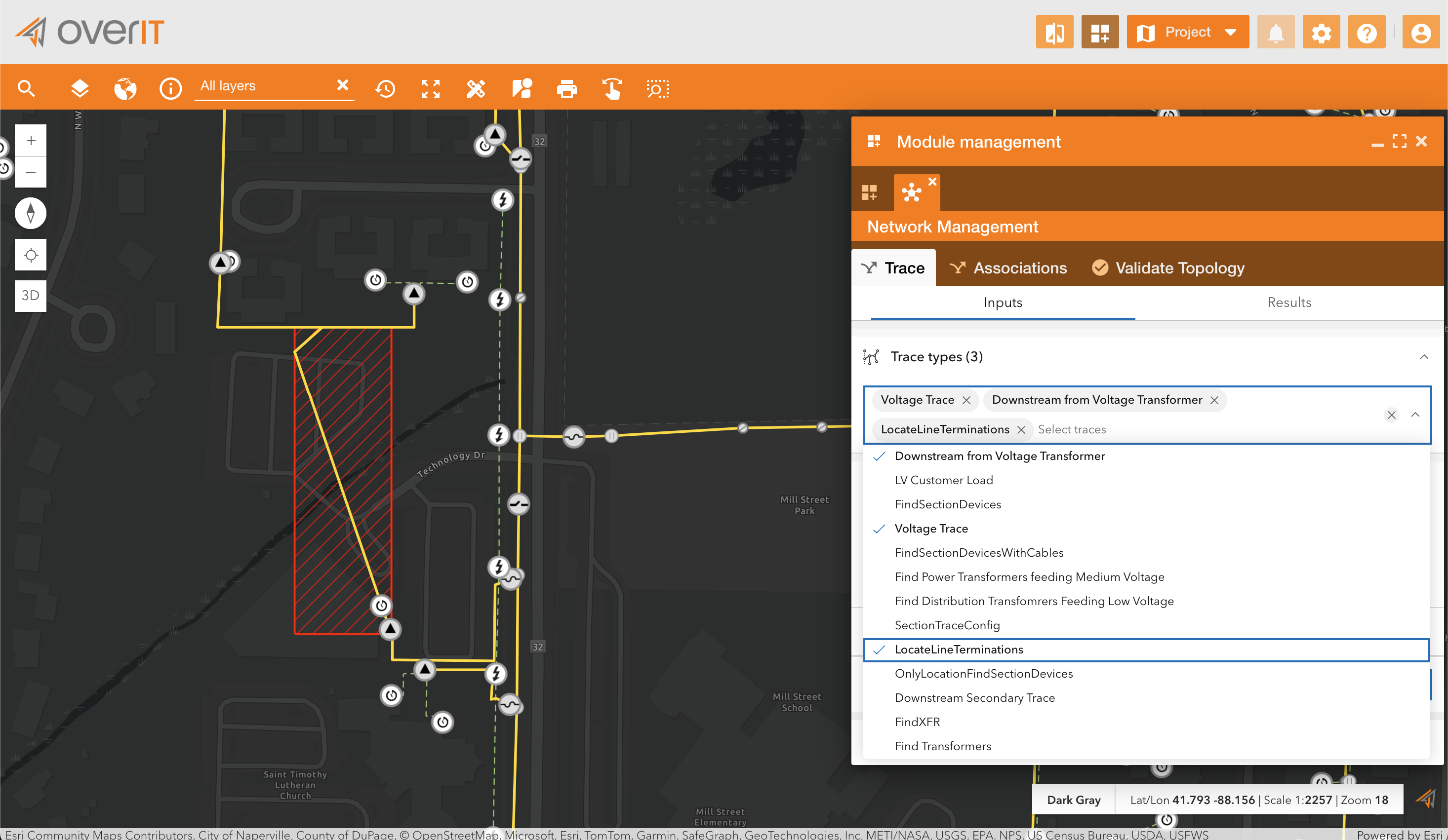
Steps to Perform a Trace
-
Select Trace Types:
-
Users can select multiple trace types from the list available in the Trace Types dropdown.
-
Examples of trace types include:
-
Voltage Trace
-
Downstream from Voltage Transformer
-
Locate Line Terminations
-
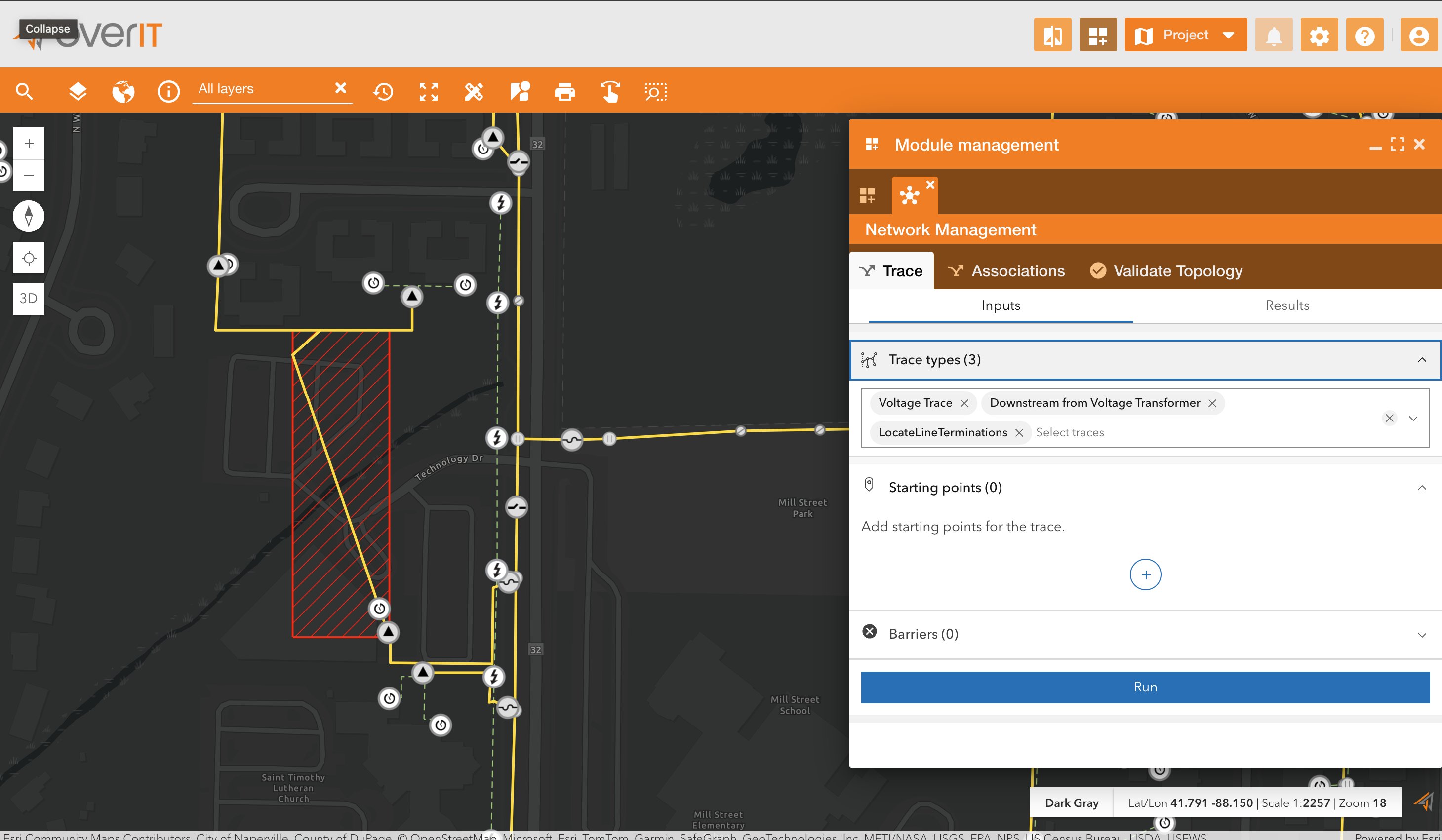
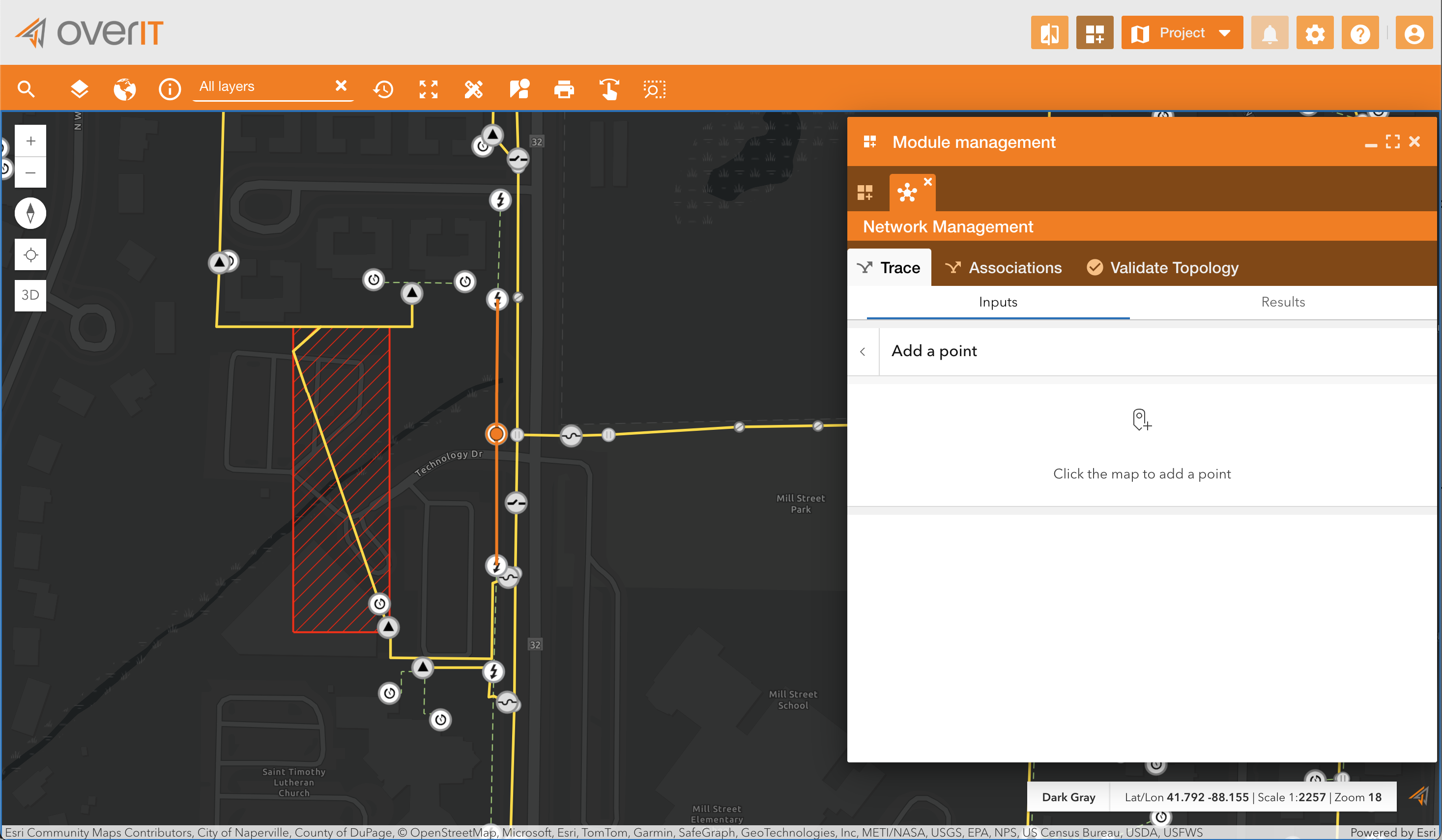
Add Starting Points:
-
Click the + icon to add a starting point for the trace.
-
Select a point on the map to define the starting location.
-
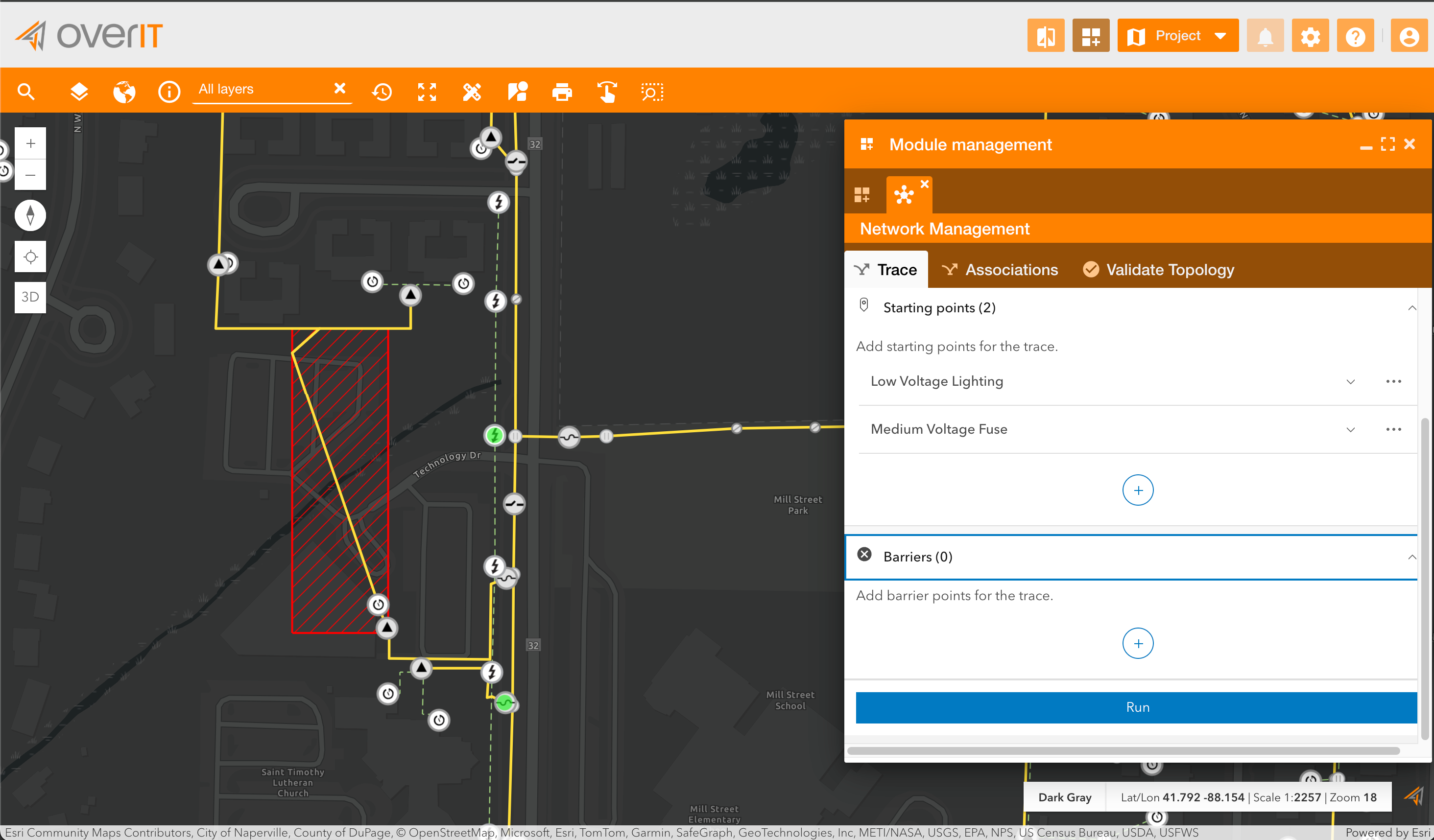
Add Additional Points:
-
Add at least one more starting point by repeating the process.
-
Multiple points can be used for more complex traces.
-
Add Barriers (Optional):
-
Users can define barriers to limit the trace’s scope by clicking the + icon under the Barriers section.
-
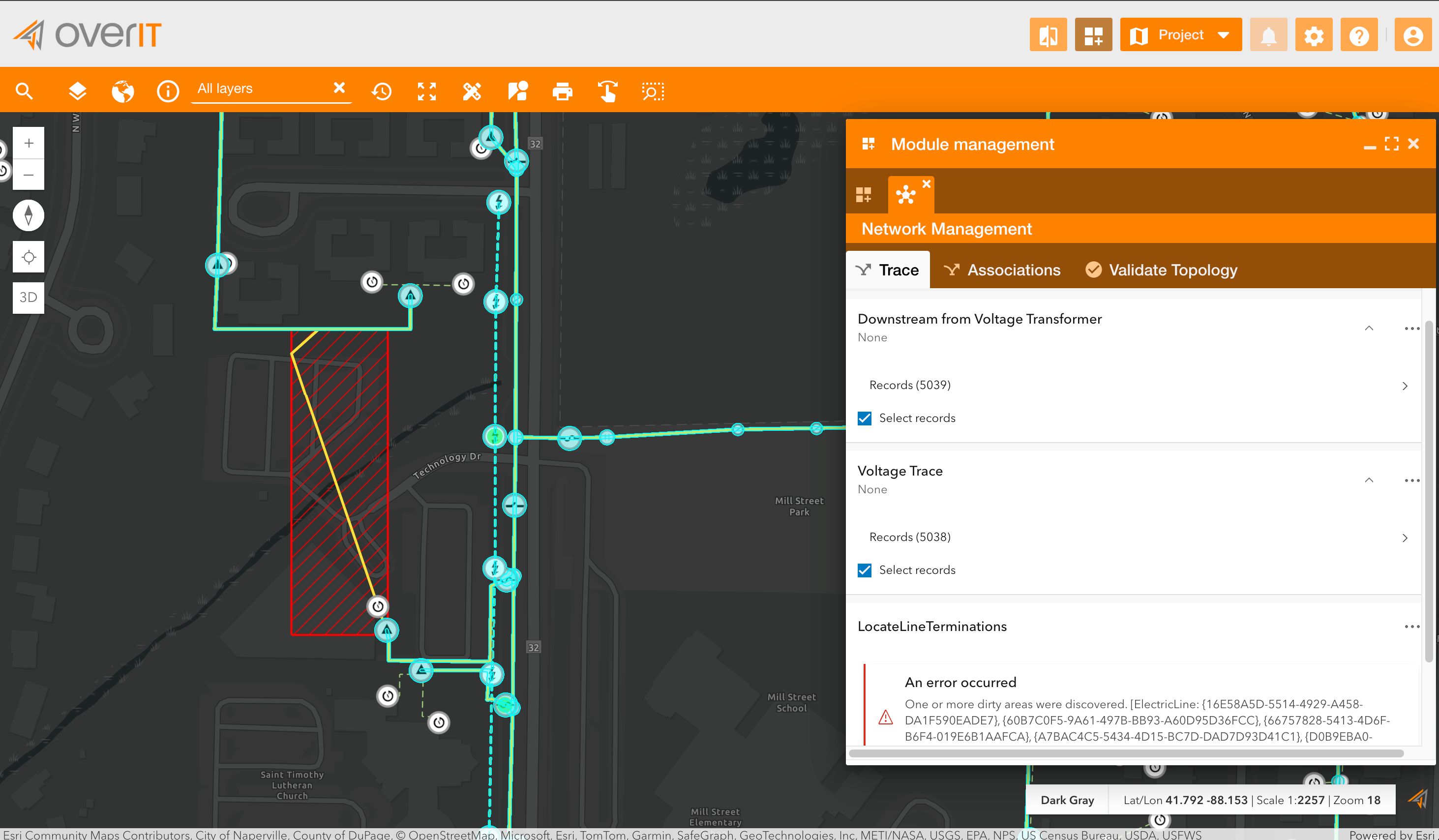
Run the Trace:
-
Click the Run button to start the tracing process.
-
The system processes the trace and displays the results.
-
View Results:
-
The results of the trace are displayed, highlighting the traced elements on the map.
-
Any errors, such as dirty areas requiring validation, are also displayed.
2. Associations
The Associations tab provides tools for managing relationships between network elements. In the ESRI Utility Network model, associations define how various components, such as lines, devices, and junctions, interact and connect:
-
Structural Associations: Represent the physical relationships between assets.
-
Connectivity Associations: Define how assets are connected within the network.
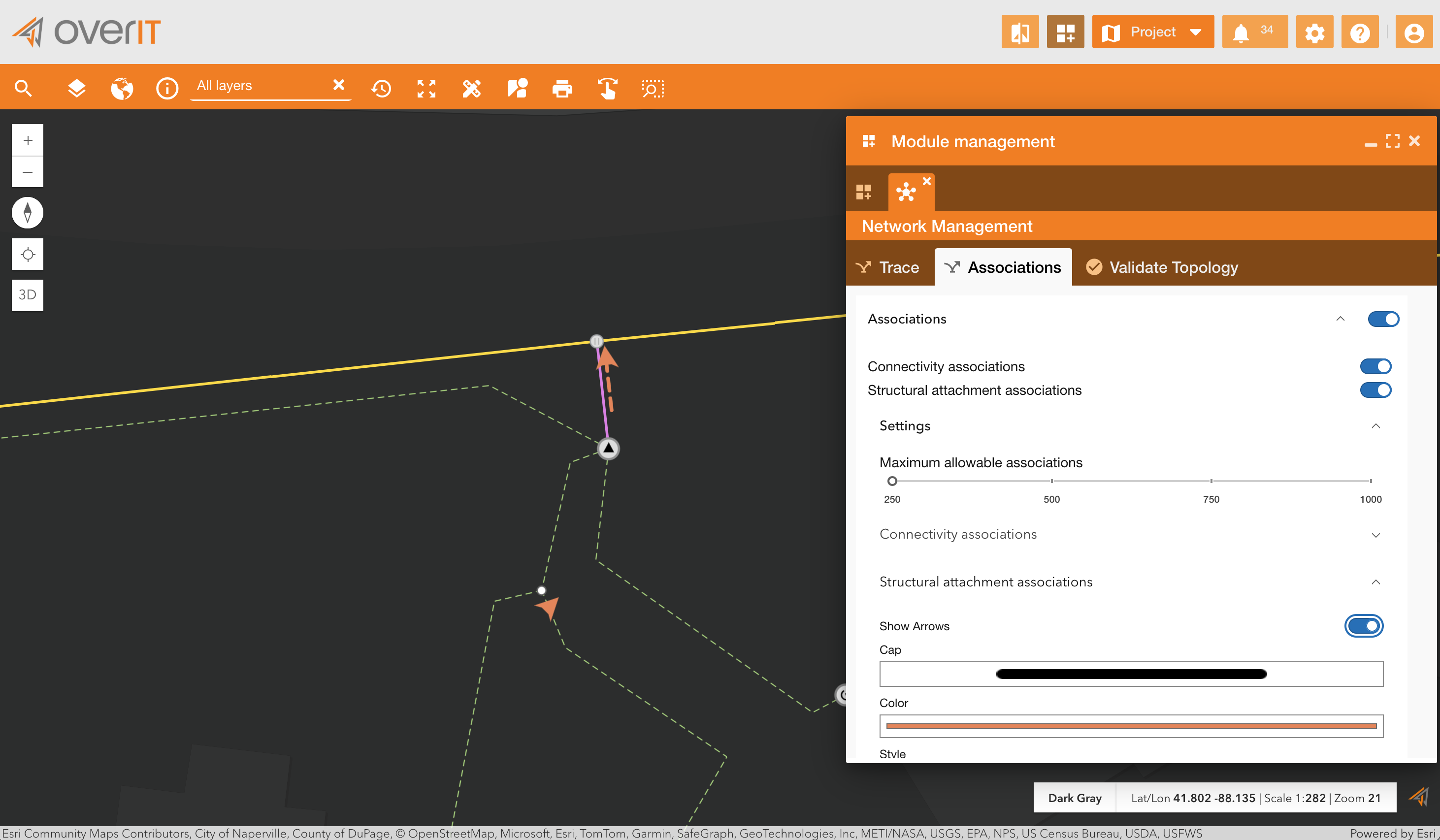
This tab ensures users can manage these relationships efficiently to maintain network integrity.
By enabling the Associations switch, the user can view how objects are associated. They can filter to display only structural or connectivity associations and choose how to represent them. In the example, associations are shown as dashed orange lines with arrows.
3. Validate Topology
The Validate Topology tab allows users to ensure that the network topology adheres to defined rules and standards. Topology validation is critical for:
-
Identifying and resolving errors in the network structure.
-
Ensuring accurate data integrity for operational workflows.
-
Verifying the connectivity and configuration of all network elements.
How to Use:
-
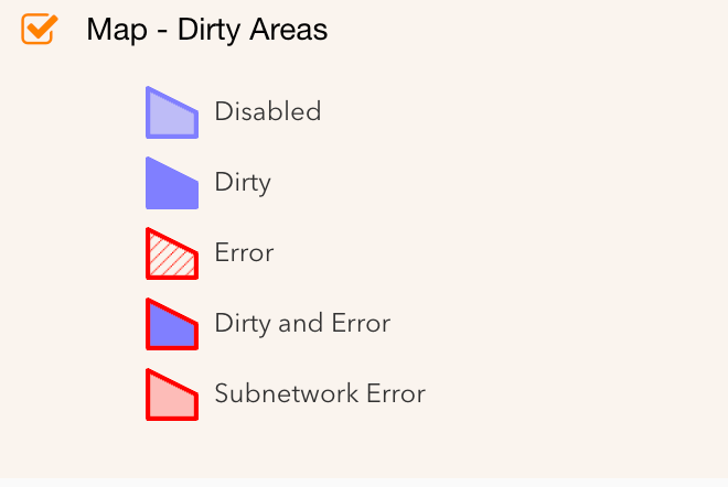
Identify Dirty Areas:
-
After making edits, areas requiring validation are marked as Dirty Areas. Dirty areas can be of different types. For example, in our test case, this is the symbology used:
-
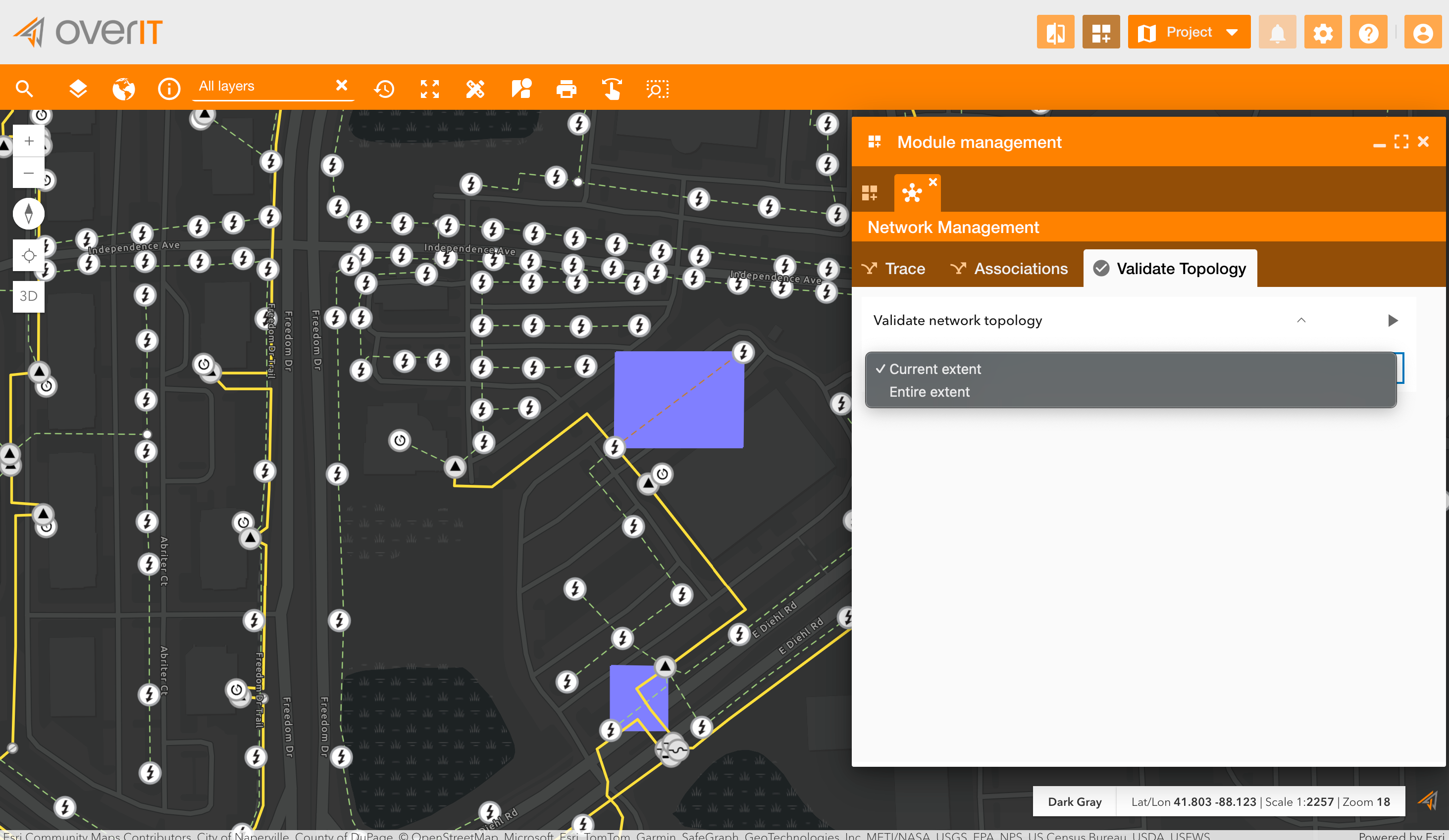
Select Validation Scope:
-
Choose whether to validate:
-
Current Extent: The visible portion of the map.
-
Entire Extent: The entire network.
-
Run Validation:
-
Click the Run button to initiate the validation process.
-
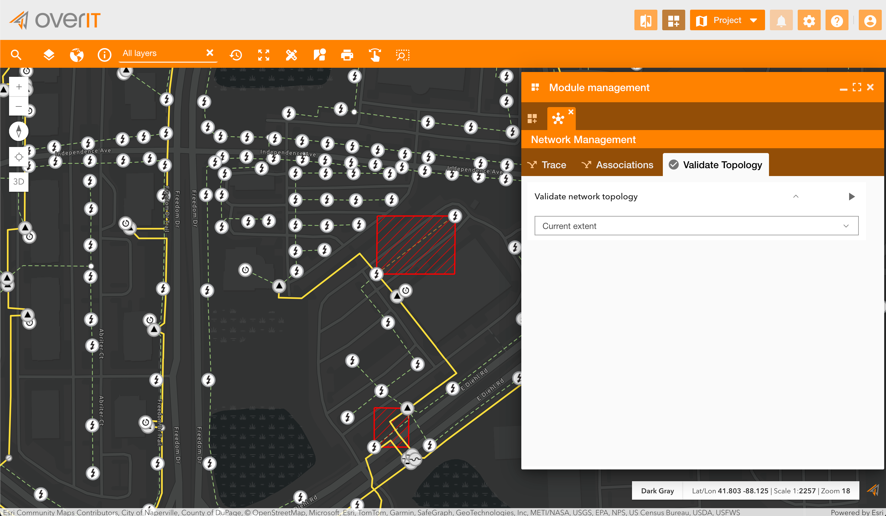
View Results:
-
The system highlights errors on the map as red-marked areas.
-
Errors indicate areas requiring further adjustments to conform to topology rules.
Benefits
-
Comprehensive Network Management: Provides end-to-end tools for editing, tracing, and validating utility networks.
-
Ease of Use: Simple configuration and user-friendly interface for network operators.
-
Focused Work Environment: Exclusive mode ensures tasks are performed without interruptions.
-
Seamless ESRI Integration: Built to work directly with the Utility Network data model, leveraging its full capabilities.
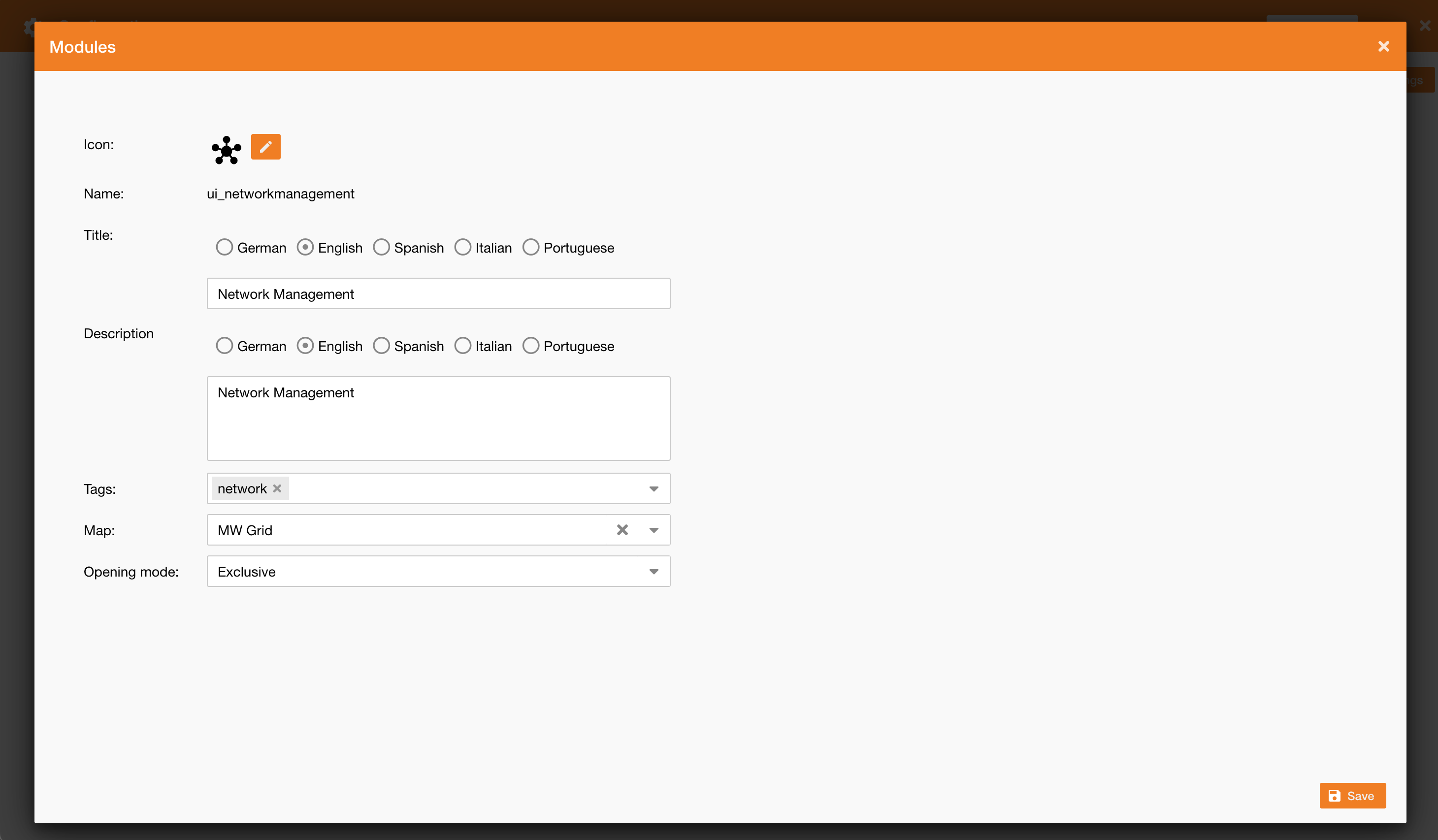
How to Configure the Module
-
Navigate to Control Panel > System > Modules.
-
Click on the Add Module button and select the ui_networkmanagement module.
-
Configure the module:
-
Add a title and description (e.g., “Network Management”).
-
Assign relevant tags (e.g., “network”).
-
Select a compatible web map using the Utility Network data model.
-
Set the opening mode to Exclusive for focused workflows.
-
Save the configuration.